
PicoProbe PCB kit
We have ✅ 1 available of the PR-FC-001 in our Sydney warehouse.
Turn your Raspberry Pi Pico into a debug probe
This PCB is designed to turn a Pico into a nice debug probe using the PicoProbe software.
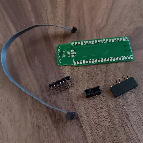
The kit provides everything you need to turn a Raspberry Pi Pico into a debug probe (Raspberry Pi Pico not included):
- The Picoprobe-PCB
- 1x cortex-M SWD 10pin header
- 1x cortex-M SWD 10pin ribon cable
- 1x 6 pin male header
- 1x 6 pin female header
Mounting options
There are two ways to mount a Raspberry Pi Pico on the Picoprobe-PCB. You can either solder it directly for a slim/compact result (right), or use header to be able to re-use the Pico on other projects (left).
Install the Picoprobe software
- Either get the picoprobe .uf2 binary from the release here or compile it yourself from sources here.
- Hold the BOOTSEL button on the Pico, then connect to your computer using a micro USB cable.
- Drag and drop the UF2 file on to the RPI-RP2 drive.
- You should be good to go.
Plug the picoprobe SWD pin to the Pico that you want to debug
Build Raspberry Pi's openocd
$ sudo apt install automake autoconf build-essential texinfo libtool libftdi-dev libusb-1.0-0-dev
$ git clone https://github.com/raspberrypi/openocd.git --branch picoprobe --depth=1 --no-single-branch
$ cd openocd
$ ./bootstrap
$ ./configure --enable-picoprobe
$ make -j4
Run openocd
$ ./src/openocd -s tcl -f interface/picoprobe.cfg -f target/rp2040.cfg
Debug!
Now that openocd is connected, you can start debugging with GDB for instance.
$ arm-eabi-none-gdb
(gdb) target extended-remote :3333
Case
Documentation
The PicoProbe PCB kit appears in the following collections:
SKU PR-FC-001
by Little Bird