
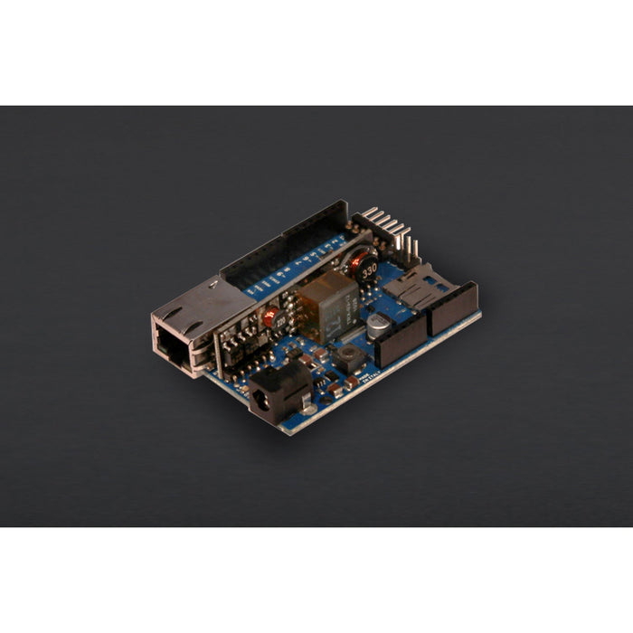
Arduino Ethernet with PoE module
The Arduino Ethernet is a microcontroller board based on the ATmega328. It has 14 digital input/output pins, 6 analog inputs, a 16 MHz crystal oscillator, a RJ45 connection, a power jack, an ICSP header, and a reset button.
NB: Pins 10, 11, 12 and 13 are reserved for interfacing with the Ethernet module and should not be used otherwise. This reduces the number of available pins to 9, with 4 available as PWM outputs.
An optional Power over Ethernet module can be added to the board as well.
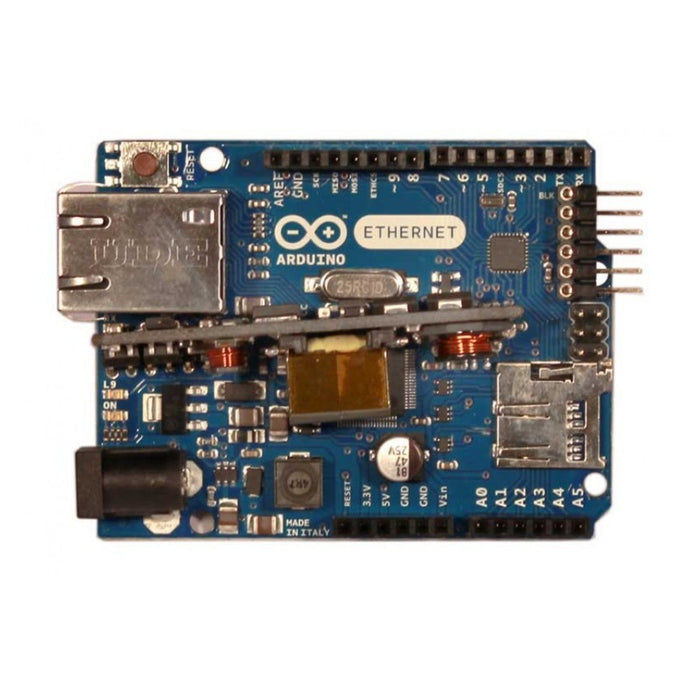
The Ethernet differs from other boards in that it does not have an onboard USB-to-serial driver chip, but has a Wiznet Ethernet interface. This is the same interface found on the Ethernet shield.
An onboard microSD card reader, which can be used to store files for serving over the network, is accessible through the SD Library. Pin 10 is reserved for the Wiznet interface, SS for the SD card is on Pin 4.
A six pin header can be connected to an FTDI breakout board or USB Serial board to provide USB power and communication to the board.
Power
The board can also be powered via an external power supply, an optional Power over Ethernet (PoE) module, or by using a FTDI cable/USB Serial connector.
External power can come either from an AC-to-DC adapter (wall-wart) or battery. The adapter can be connected by plugging a 2.1mm center-positive plug into the board's power jack. Leads from a battery can be inserted in the Gnd and Vin pin headers of the POWER connector.
The board can operate on an external supply of 6 to 20 volts. If supplied with less than 7V, however, the 5V pin may supply less than five volts and the board may be unstable. If using more than 12V, the voltage regulator may overheat and damage the board. The recommended range is 7 to 12 volts.
SPECIFICATIONS
- Microcontroller: ATmega328
- Operating Voltage:5V
- Input Voltage (recommended):7-12V
- Input Voltage (limits):6-20V
- Digital I/O Pins:14 (of which 4 provide PWM output)
- Arduino Pins reserved
- 10 to 13 used for SPI
- 4 used for SD card
- 2 W5100 interrupt (when bridged)
- Analog Input Pins6
- DC Current per I/O Pin:40 mA
- DC Current for 3.3V Pin:50 mA
- Flash Memory32 KB (ATmega328) of which 0.5 KB used by bootloader
- SRAM2 KB (ATmega328)
- EEPROM1 KB (ATmega328)
- Clock Speed16 MHz
- W5100 TCP/IP Embedded Ethernet Controller
- Power Over Ethernet ready Magnetic Jack
- Micro SD card, with active voltage translators
DOCUMENTS
SHIPPING LIST
- Arduino Ethernet w/o PoE module x1
The Arduino Ethernet with PoE module appears in the following collections:
SKU DF-DFR0148
by Little Bird